


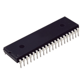
CD4070 – An IC with Four XOR Gates

The CD4070 is a CMOS chip with four XOR gates. Because each gate has two inputs and it has four gates inside, it’s usually called a Quad 2-Input XOR Gate.
XOR means exclusive OR, and will only give a HIGH output if one of the inputs is HIGH and the other is LOW. Or to say it in another way: The output from an XOR gate will be HIGH only if the inputs are not equal.
Pin Overview
| Pin Name | Pin # | Type | Description |
|---|---|---|---|
| VDD | 14 | Power | Supply Voltage (+3 to +15V) |
| GND | 7 | Power | Ground (0V) |
| A1 to A4 | 1, 5, 8, 12 | Input | Inputs A of the four XOR gates |
| B1 to B4 | 2, 6, 9, 13 | Input | Inputs B of the four XOR gates |
| Q1 to Q4 | 3, 4, 10, 11 | Output | Outputs from the four XOR gates |
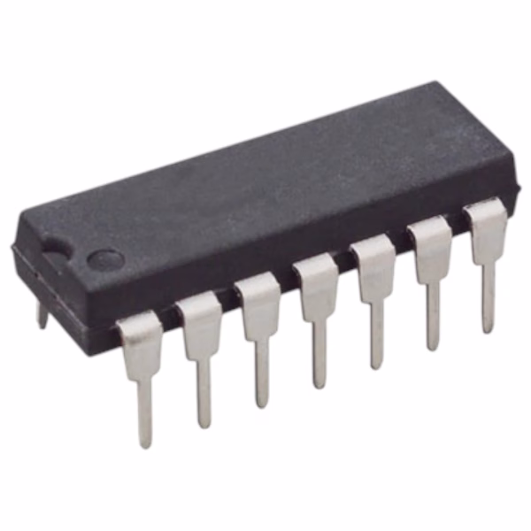
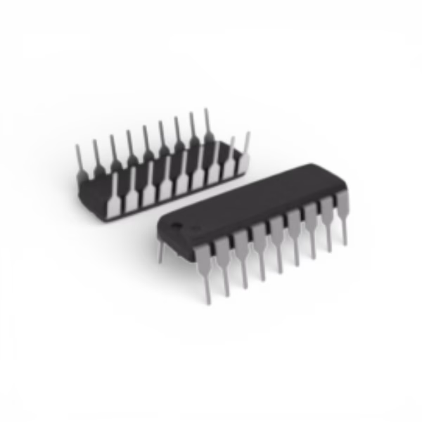
Pin overview for the 4070 IC
What is an XOR gate?
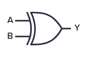
The XOR gate outputs HIGH if its two inputs are not equal. So if one of the inputs (both not both!) is HIGH, the output will be HIGH. It’s one of the basic logic gates.
| Input A | Input B | Output Y |
|---|---|---|
| 0 | 0 | 0 |
| 0 | 1 | 1 |
| 1 | 0 | 1 |
| 1 | 1 | 0 |
XOR Gate Truth Table
How To Use the CD4070?
Like with all ICs in the 4000 series, you need a power supply voltage of 3 to 15V. Some versions of the chip support up to 20V. Check the datasheet of your version of the chip for exact values.
To be able to use any of the XOR gates in the chip, you need to first connect the VDD pin to the positive supply terminal and the GND pin to the negative supply terminal.
The A and B pins are the inputs to the four XOR gates in the IC.
The Q pins are the outputs from the XOR gates.

Technical Specifications
Physical |
|
Case/Package |
PDIP |
Contact Plating |
Gold |
Mount |
Through Hole |
Number of Pins |
14 |
Technical |
|
Ambient Temperature Range High |
125 °C |
High Level Output Current |
-4.2 mA |
Input Capacitance |
5 pF |
Logic Function |
XOR |
Low Level Output Current |
4.2 mA |
Max Junction Temperature (Tj) |
150 °C |
Max Operating Temperature |
125 °C |
Max Output Current |
6.8 mA |
Max Supply Voltage |
18 V |
Min Operating Temperature |
-55 °C |
Min Supply Voltage |
3 V |
Number of Bits |
4 |
Number of Channels |
4 |
Number of Circuits |
4 |
Number of Elements |
4 |
Number of Gates |
4 |
Number of Input Lines |
2 |
Number of Inputs |
2 |
Number of Output Lines |
1 |
Number of Outputs |
1 |
Output Current |
6.8 mA |
Propagation Delay |
100 ns |
Quiescent Current |
5 µA |
Schmitt Trigger Input |
No |
Termination |
Through Hole |
Turn-On Delay Time |
100 ns |


Reviews
Clear filtersThere are no reviews yet.